How to halve redstone signal strength?
I'd like the output signal to be half the input signal strength.
I was able to use the 'lookup table' approach, which can convert pretty much any input to any output, but is bulky, noisy, somewhat slow, and quite expensive.
Is there a neater, more compact, or faster way to convert input signal strength 0-15 into range 0-8 (or similar, small off-by-one changes allowed, e.g. 0,1->0; 14,15->7).
Bonus: divide by a different number?
83 Answers
What about this?When you make your input two units stronger, your output increases by one.
Edit:
This is rather slow, because it takes up to 8 ticks (one for the last repeater plus one for each of the following comparators) to update the output.
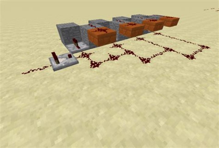
Inspired by Fabian Rölling's faster (only one tick) solution, I found out that lining up the repeater's output to adjacent blocks leads to an even more compact solution for the division by two:
Note that the redstone signal can climb up slabs but not down!
Each repeater is reached in two steps more compared to the previous repeater. The last repeater reached is crucial for the result. Because the output blocks of the repeaters are adjacent, the signal's power is reduced by one for each unused repeater passed.
From this pattern, we can derive solutions for a division by any number, for example by three:
Please note that the input to the repeater can come from behind the adjacent solid block. Here each repeater is reached in three steps more compared to the previous one.
The division by five turns out to be very simple:
I built a gigantic complex circuit that converted signal strength to time using comparator fadeout and then back to signal strength using locking repeaters, then I built a simpler circuit based on Xisuma's item frame rotation detector, which was still quite bulky and complicated looking… and then I had an epiphany and just used a bit of redstone dust.
This is all. The leftmost redstone dust at the top is the input, the one on the bottom right above the sign is the output. The trick is to just snake around the redstone line more and more the weaker the signal is.
Only the repeater corresponding to the strongest detected signal (furthest to the right) matters for the power level of the output, because for example a power level of 8 overwrites all from 1 to 7 that come from the repeaters further on the left. Only every second repeater is needed in that case, because the other ones would just go to the same line anyway (thanks to Gerhard for that hint). Every pair of initial redstone dusts for two neighbouring repeaters is connected, so that the signal strength decreases by 1 when going to the output from the first pair, but not the second pair. For every pair the redstone line has to snake back and forth one block more than the last one, so that the signal strength at the output decreases by 2 from that.
This should be buildable just from the picture, but here's a structure anyway:
2I've finally managed something that doesn't depend on a lookup table of one form or another and is somewhat neat.
Dual Fader - two fader circuits, the top one fading at 2 levels per (2rt) period, the bottom one fading by one but only while the top one still has power.
There's a reset that clears any residual power before the new input is latched, and there's output enable feature that keeps output unpowered while the calculation is in progress.
Due to timing dependencies it has a small, rather harmless quirk - maps 0->0, 1->1, 14->8, 15->9. Making the input signal 1 weaker (just adding one redstone dust on input)
Following: top view of the entire device, and top view onto the bottom fader (top fader removed).
The right side of the image is a monostable circuit that activates on input change and passes input to the divider, then cuts it off to enable calculation. It also activates the two reset lines (above). The central part - two comparators aimed into solid blocks - create analog memory cells. Combined with comparators (bottom sides of the images) subtracting signal strength 2 or 1 respectively (produced by reading the appropriately filled composters) these comprise the fader circuits.
The composter of the lower circuit is lowered into position by a sticky piston activated by signal from the upper circuit. The left side has a piston raising a solid block to disable output while calculation is in progress and lowering it between two comparators to enable output.